Final render & Technical sheet
dinsdag 18 mei 2010
Further enhancements
As mentioned below, the suggestions for a passage with a more open feel were taken into account. On top of that, I was thinking of some modifications to keep out bikes more effectively. I came up with two:

This setup is even more simple in construction, while preserving all advantages of the one sketched above:

- An extra turn would not only make it even harder for bikes, but would also make the users leave the same direction as they came in.
- As a last resort, if real life usage shows the inadequacy to block bikes out, one or two turnpike could be added as shown below. This will definitely tackle the problem completely, however it does also erase the original elegance.

This setup is even more simple in construction, while preserving all advantages of the one sketched above:

First prototype
The first prototype was completely cut out of PU-foam by a CNC machine, available at our school. Now, my lack of experience with the machine and the program to convert 3D-models to usable CNC-models caused an incomplete prototype. However the image below shows some idea to what was intended.

The jury gave some very interesting comments on the solution and were also very taken by its simplicity and ease of use. First of all, the setup is quite confined. A suggestion was to no longer work with a solid structure, but more with frames. I liked this idea very much, as this would create a much more open feeling. These frames could be used to hold plants as well, which was suggested too. This change wouldn't affect the effectiveness of the system, but would make it more attractive.
My own concerns were: will this gate function as it is supposed to? My biggest fear was that bikes still would be able to be forced through.
Meeting the objectives - basic idea
My idea to meet the new set of objectives works as follows:


How are bikes declined access (and wheelchairs allowed):
- Take a rough profile of a wheelchair (with user)
- Drag it through a solid block with a very short turn


How are bikes declined access (and wheelchairs allowed):
- The passage is at its smallest at about 1.1m, which is the height of the handlebars on regular bike.
- There is a very short turn, which is very hard to impossible to take with a bike.
- It is quite narrow, so the bicyclist can't walk beside his bike, making it very hard to push it through.
- There's extra space provided for the wheeling action. The danger of hurting hands while passing through is hereby reduced.
- In the short turn, some extra leg space is built in. The feet of a wheelchair user make the biggest circle while turning. So by creating leg space at the bottom, the overall turning radius is kept at a minimum.
- No force has to be applied anywhere, everyone can just wheel or walk on.
- The initial profile doesn't reveal any intention towards specials efforts for the disabled or keeping bikes out.
Redefining the objectives
The existing solution did not only lack ease of use. When we take a closer look to the problem, there are other flaws: it sends a (somewhat too obvious) message of keeping some people out and even more so keeping access available to the 'disabled', it doesn't allow a fluent passage of people.
- Wheelchair users do not like to be stigmatized (yet again) by a gate that clearly is designed to allow them access, while keeping others out
- A system which allows only one person at a time go through, will fail with large crowds and will cause congestion
- The system should be easy to use: no or very little force to be applied
- No clear distinction between those who can and those who can't get access
- The system should allow a smooth passage of numerous visitors
First idea
The objective is to allow regular pedestrians and wheelchair user access to certain areas (sport terrains, parks, ...), while keeping bicycles and motorcycles out. This challenge was laid upon us by the city of Kortrijk, which already has a solution, however not an optimal one. It is shown below and is called 'de klauw'.

My first idea was to simply improve this setup, as it already does quite a good job. The main problem is the force which the wheelchair user has to apply to open and close the claws. A solution would be to make this happen automatically. Since no electronics or machinery are allowed for this challenge, I thought of using the moving weight of those passing through. A mechanism underneath the setup could open the claws to one side where a force is applied by the weight of the user. The force moves to the center of the claws, causing it to open to the other side.

My first idea was to simply improve this setup, as it already does quite a good job. The main problem is the force which the wheelchair user has to apply to open and close the claws. A solution would be to make this happen automatically. Since no electronics or machinery are allowed for this challenge, I thought of using the moving weight of those passing through. A mechanism underneath the setup could open the claws to one side where a force is applied by the weight of the user. The force moves to the center of the claws, causing it to open to the other side.
maandag 29 maart 2010
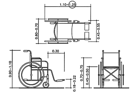
Bike & wheelchair dimensions
Bicycle Dimensions
Dinbelg Data: (Dinbelg: Dimensions of/for wheelchair users)
Technical Data:

(http://www.un.org)
Critical wheel chair dimensions:
General dimensions on Accesscode.info
- Vandewalle: vehicle dimension laws (Max Bicycle Width: 75cm)
- WikiAnswers: Average bicycle (Average Bicycle Width: 65cm & Length: 180cm)
Dinbelg Data: (Dinbelg: Dimensions of/for wheelchair users)
Width of passage | 80 minimal |
|
| 90 optimal |
| Vertical reach | 120 maximal |
| Bend down | 40 minimal |
| Turning radius | 150 wheelchair user |
|
| 190 with companion |
| Operation controls | 90 – 120 cm |
| Supporting bar | 85 – 90 cm |
Technical Data:

(http://www.un.org)
Critical wheel chair dimensions:
General dimensions on Accesscode.info
dinsdag 23 maart 2010
Special features
Extra high positions with an extra board:

Staircase-like holes for easy height adjustment:

(http://www.youtube.com/watch?v=3yITovyzYV4)
Unremovable bolts:


Staircase-like holes for easy height adjustment:

(http://www.youtube.com/watch?v=3yITovyzYV4)
Unremovable bolts:


Labels:
ceder,
inclined reading / laptop stand
Design improvements


Design improvements:
- L-shape profile part to ensure flatness of the surface & general strength
A L-shaped part is glued to both sides of the surface - Cedar plugs replaced by steel bolts and a cedar cap for concealing the metal
The head of a 8cm bolt, with 2,5cm of thread, was removed. A matching nut was installed. The threaded part of the bolt was forced & glued into a small cedar cube. This whole was installed into the top board, with the nut glued & sunk into the L-shaped profile. This makes sure that the bolt can never be removed, on side is bound by the end of the thread, the other side by the cedar cap. - Staircase-like holes for easy height adjustments
The top hole is the deepest of all, the one beneath a little less deep, and so on. That way, unscrewing the bolts by turning the wooden cubes, will lower the stand step by step(1,5cm each). No more searching for the right hole! - No front board
The front board was removed to simplify the design - Inclination angle & back board angle
Both angles were adjusted to prevent the stand to fall forward and to make it stay upright on the back board as well (so that the user surface of the stand is positioned almost vertically)
- Two small ridges to hold documents better
- Holes all over the surface for better laptop ventilation
- Rubber feet for more grip on smooth surfaces
Labels:
ceder,
inclined reading / laptop stand
Ergonomic considerations

What advantages could this product provide?
- When working behind a computer screen, the top of the screen should be at the same height as the eyes. Otherwise stress is put on the neck by looking upwards.
- Reading a document or typing on a flat surface requires leaning forward. The inclination angle of the stand prevents this. Stress, that would reside on the back, is lifted.
- Typing on a slightly inclined keyboard causes less tension.
Dinbelg & Ergonomiesite
Ergonomic calculations:
(These calculations are made based on data from Dinbelg)
- The average table is 72cm high
- 99% of (belgian) adults are over 107,4cm high (eye-height while sitting)
- 99% of (belgian) adults are less than 148,2cm high (eye-height while sitting)
- The average laptop is about 30cm high
Labels:
ceder,
inclined reading / laptop stand
Prototype
First prototype of the laptop stand:


Design issues:


Design issues:
- Connections between the different parts with cedar plugs are too weak.
- The surface of the stand is not flat, because the three boards hang.
- Finding the hole to insert the plugs makes it hard to alter the height.
Labels:
ceder,
inclined reading / laptop stand
donderdag 11 maart 2010
maandag 8 maart 2010
zondag 28 februari 2010
Idea Selection
These ideas from the exploration phase transfer to the next:
- Modular wall covering
- Inclined reading / laptop stand
- (dog house)
maandag 22 februari 2010
Abonneren op:
Posts (Atom)


